
How to Make a Peace Pendant
Tue Mar 22 2016
Rechargeable Sound Reactive LED Peace Pendant — Overview
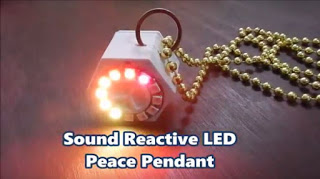
With all the madness going on in the world right now, a LED sound reactive peace pendant would help radiate some love. Below are instructions on how you can make this cool project.
The circuitry for this wearable project isn’t that complex, and the 3D printed enclosure will provide a nice pendant that you can wear to your next party or event.
Features:
- Sound reactive
- Rechargeable
- On/Off switch
- Programmable
Parts
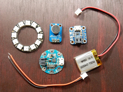
Most of the parts available through Adafruit. Their Weekly shows have 10% off coupons which are a great deal to pick up these parts.
- Arduino or Adafruit Gemma
- NeoPixel Ring (12 LEDs)
- Switch
- #4 3/8 inch Screws (x2) or similar
- Li-Po battery 3.7V 150mAh
- Lipoly battery charger
- Mic Amp
- Necklace and ring
- Micro USB cable for programming/charging
- 22 AWG hook-up wire or any other suitable wire
Tools and Supplies:
- 3D printer with filament
- Soldering Iron with solder
- Wire Strippers and pliers
- Hot glue gun and super glue
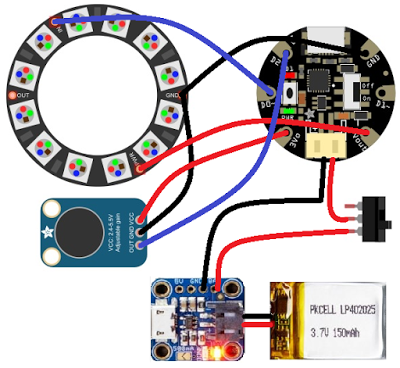
Circuit Diagram
3D Printing
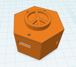
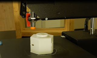
Please download the .stl from Thingiverse (thing:1134027) and print out the enclosure and lid. Some support material is required, but nothing intense. Printed in 1.75mm PLA on a PrintrBot Simple Metal at about 220°C. Repetier Host was the 3D printing software using Slic3r. The enclosure was designed in Tinkercad, on a PRINTinZ Zebra plate.
Assembly
The pendant assembly isn’t that complicated. The enclosure was designed to comfortably hold the above-mentioned parts without much hassle. Please see the video for the assembly summary.
-
Start by soldering short lengths of hook-up wire to the LED ring. The front face of the enclosure was designed with holes aligned to the LED ring wire solder points. Mount the ring onto the face of the enclosure and slide the wires into the enclosure. You could use some adhesive to anchor the ring, but this isn’t required since the fit is tight enough to hold it in place.
-
Solder a short piece of wire to one of the far-end pins on the slide switch, and connect that to the BAT of the LiPo charger. Solder the RED lead of the JST-PH lead onto the middle pin of the slide switch. Please see the circuit diagram above for an illustration.
-
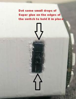
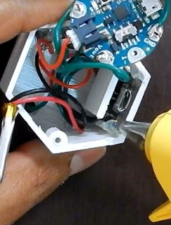
Push the slide switch into the opening on the side of the enclosure. You could use a small amount of super glue to the edges — be careful not to encircle the entire switch with glue or the switch won’t work! You could also use hot glue on the inside to hold the switch in place.
-
Solder the Black GND lead of the JST-PH lead to the GND on the LiPo charger. Ensure the wires soldered to the LiPo charger are attached to the TOP side of the charger so it sits flush when inserted into the enclosure.
-
Solder short lengths of hook-up wire to the MIC amp. The connections are shown in the circuit picture above.
-
Solder the LED ring wires to the Arduino Gemma according to the circuit diagram.
-
Insert the battery lead into the LiPo charger and seat the charger in the enclosure. Use some hot glue to secure the charger on the enclosure — this matters since the USB cable will constantly be attached and detached for charging.
-
At this point, the soldering is complete. Let’s program the Arduino before final assembly. You will need the Adafruit NeoPixel library for the sketch. Download the Arduino sketch from GitHub and load it onto the Gemma. Once the sketch is loaded, test the flashing of the LEDs by tapping the mic. The LEDs should react to the sound. If it does not work, check your wiring and ensure your Arduino sketch is loaded correctly.
-
Once the circuit is verified to be working, button-up your project by putting the LiPo battery in the enclosure and pass the JST lead under the charger partition built into the enclosure.
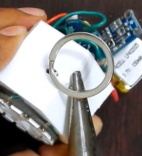
- If you want to insert a ring to hang the enclosure on a lanyard, now would be the time before final assembly. I used a keyring and slid that on the enclosure.
- Let’s do the final assembly by inserting the battery first, then the Arduino Gemma. Insert a small plastic spacer before putting in the MIC to prevent any short circuits. Close the enclosure using 2 x #4 3/8 inch screws with the 3D printed lid. Ensure the USB charging port lines up with the opening. Attach a lanyard, beaded necklace, or whatever you like.
Arduino Code
This sketch works on both the original GEMMA (8 MHz) and GEMMA M0. You’ll need the Adafruit NeoPixel library installed first — see All About Arduino Libraries if you need a refresher on installing libraries.
// SPDX-FileCopyrightText: 2017 Limor Fried for Adafruit Industries
//
// SPDX-License-Identifier: MIT

#include <Adafruit_NeoPixel.h>

#define N_PIXELS  12  // Number of pixels you are using
#define MIC_PIN   A1  // Microphone is attached to Trinket GPIO #2/Gemma D2 (A1)
#define LED_PIN    0  // NeoPixel LED strand is connected to GPIO #0 / D0
#define DC_OFFSET  0  // DC offset in mic signal - if unusure, leave 0
#define NOISE     100  // Noise/hum/interference in mic signal
#define SAMPLES   60  // Length of buffer for dynamic level adjustment
#define TOP       (N_PIXELS +1) // Allow dot to go slightly off scale

byte
  peak      = 0,      // Used for falling dot
  dotCount  = 0,      // Frame counter for delaying dot-falling speed
  volCount  = 0;      // Frame counter for storing past volume data

int
  vol[SAMPLES],       // Collection of prior volume samples
  lvl       = 10,     // Current "dampened" audio level
  minLvlAvg = 0,      // For dynamic adjustment of graph low & high
  maxLvlAvg = 512;

Adafruit_NeoPixel  strip = Adafruit_NeoPixel(N_PIXELS, LED_PIN, NEO_GRB + NEO_KHZ800);

void setup() {
  memset(vol, 0, sizeof(vol));
  strip.begin();
}
void loop() {
  uint8_t  i;
  uint16_t minLvl, maxLvl;
  int      n, height;
  n   = analogRead(MIC_PIN);                 // Raw reading from mic
  n   = abs(n - 512 - DC_OFFSET);            // Center on zero
  n   = (n <= NOISE) ? 0 : (n - NOISE);      // Remove noise/hum
  lvl = ((lvl * 7) + n) >> 3;    // "Dampened" reading (else looks twitchy)

  // Calculate bar height based on dynamic min/max levels (fixed point):
  height = TOP * (lvl - minLvlAvg) / (long)(maxLvlAvg - minLvlAvg);

  if(height < 0L)       height = 0;      // Clip output
  else if(height > TOP) height = TOP;
  if(height > peak)     peak   = height; // Keep 'peak' dot at top

  // Color pixels based on rainbow gradient
  for(i=0; i<N_PIXELS; i++) {
    if(i >= height)
       strip.setPixelColor(i,   0,   0, 0);
    else
       strip.setPixelColor(i,Wheel(map(i,0,strip.numPixels()-1,30,150)));
    }

   strip.show(); // Update strip

  vol[volCount] = n;                      // Save sample for dynamic leveling
  if(++volCount >= SAMPLES) volCount = 0; // Advance/rollover sample counter

  // Get volume range of prior frames
  minLvl = maxLvl = vol[0];
  for(i=1; i<SAMPLES; i++) {
    if(vol[i] < minLvl)      minLvl = vol[i];
    else if(vol[i] > maxLvl) maxLvl = vol[i];
  }
  // minLvl and maxLvl indicate the volume range over prior frames, used
  // for vertically scaling the output graph (so it looks interesting
  // regardless of volume level).  If they're too close together though
  // (e.g. at very low volume levels) the graph becomes super coarse
  // and 'jumpy'...so keep some minimum distance between them (this
  // also lets the graph go to zero when no sound is playing):
  if((maxLvl - minLvl) < TOP) maxLvl = minLvl + TOP;
  minLvlAvg = (minLvlAvg * 63 + minLvl) >> 6; // Dampen min/max levels
  maxLvlAvg = (maxLvlAvg * 63 + maxLvl) >> 6; // (fake rolling average)
}

// Input a value 0 to 255 to get a color value.
// The colors are a transition r - g - b - back to r.
uint32_t Wheel(byte WheelPos) {
  if(WheelPos < 85) {
   return strip.Color(WheelPos * 3, 255 - WheelPos * 3, 0);
  } else if(WheelPos < 170) {
   WheelPos -= 85;
   return strip.Color(255 - WheelPos * 3, 0, WheelPos * 3);
  } else {
   WheelPos -= 170;
   return strip.Color(0, WheelPos * 3, 255 - WheelPos * 3);
  }
}
From the Tools→Board menu, select Adafruit Gemma M0 or Adafruit Gemma 8 MHz depending on your board. The original Gemma (8 MHz) needs the reset button pressed before clicking upload; the Gemma M0 does not.
Full source and updates: View on GitHub.
CircuitPython Code
GEMMA M0 boards can also run CircuitPython, which comes factory pre-loaded on the board. Below is CircuitPython code that works similarly to the Arduino sketch above. Plug the GEMMA M0 into USB — it will show up as a small flash drive — then edit main.py with your text editor, replacing its entire contents with the code below. The code starts running as soon as you save the file.
# SPDX-FileCopyrightText: 2017 Limor Fried for Adafruit Industries
#
# SPDX-License-Identifier: MIT

import array
from rainbowio import colorwheel
import board
import neopixel
from analogio import AnalogIn

led_pin = board.D0  # NeoPixel LED strand is connected to GPIO #0 / D0
n_pixels = 12  # Number of pixels you are using
dc_offset = 0  # DC offset in mic signal - if unusure, leave 0
noise = 100  # Noise/hum/interference in mic signal
samples = 60  # Length of buffer for dynamic level adjustment
top = n_pixels + 1  # Allow dot to go slightly off scale

peak = 0  # Used for falling dot
dot_count = 0  # Frame counter for delaying dot-falling speed
vol_count = 0  # Frame counter for storing past volume data

lvl = 10  # Current "dampened" audio level
min_level_avg = 0  # For dynamic adjustment of graph low & high
max_level_avg = 512

# Collection of prior volume samples
vol = array.array('H', [0] * samples)

mic_pin = AnalogIn(board.A1)

strip = neopixel.NeoPixel(led_pin, n_pixels, brightness=.1, auto_write=True)

def remap_range(value, leftMin, leftMax, rightMin, rightMax):
    # this remaps a value from original (left) range to new (right) range
    # Figure out how 'wide' each range is
    leftSpan = leftMax - leftMin
    rightSpan = rightMax - rightMin

    # Convert the left range into a 0-1 range (int)
    valueScaled = int(value - leftMin) / int(leftSpan)

    # Convert the 0-1 range into a value in the right range.
    return int(rightMin + (valueScaled * rightSpan))

while True:
    n = int((mic_pin.value / 65536) * 1000)  # 10-bit ADC format
    n = abs(n - 512 - dc_offset)  # Center on zero

    if n >= noise:  # Remove noise/hum
        n = n - noise

    # "Dampened" reading (else looks twitchy) - divide by 8 (2^3)
    lvl = int(((lvl * 7) + n) / 8)

    # Calculate bar height based on dynamic min/max levels (fixed point):
    height = top * (lvl - min_level_avg) / (max_level_avg - min_level_avg)

    # Clip output
    if height < 0:
        height = 0
    elif height > top:
        height = top

    # Keep 'peak' dot at top
    if height > peak:
        peak = height

        # Color pixels based on rainbow gradient
    for i in range(0, len(strip)):
        if i >= height:
            strip[i] = [0, 0, 0]
        else:
            strip[i] = colorwheel(remap_range(i, 0, (n_pixels - 1), 30, 150))

    # Save sample for dynamic leveling
    vol[vol_count] = n

    # Advance/rollover sample counter
    vol_count += 1

    if vol_count >= samples:
        vol_count = 0

        # Get volume range of prior frames
    min_level = vol[0]
    max_level = vol[0]

    for i in range(1, len(vol)):
        if vol[i] < min_level:
            min_level = vol[i]
        elif vol[i] > max_level:
            max_level = vol[i]

    # minlvl and maxlvl indicate the volume range over prior frames, used
    # for vertically scaling the output graph (so it looks interesting
    # regardless of volume level).  If they're too close together though
    # (e.g. at very low volume levels) the graph becomes super coarse
    # and 'jumpy'...so keep some minimum distance between them (this
    # also lets the graph go to zero when no sound is playing):
    if (max_level - min_level) < top:
        max_level = min_level + top

    # Dampen min/max levels - divide by 64 (2^6)
    min_level_avg = (min_level_avg * 63 + min_level) >> 6
    # fake rolling average - divide by 64 (2^6)
    max_level_avg = (max_level_avg * 63 + max_level) >> 6

    print(n)
This code requires the neopixel.py library, which comes pre-installed on a factory-fresh board. If you’ve reloaded CircuitPython, create a lib directory and download neopixel.py from GitHub.
Full source and updates: View on GitHub.
How to Use
Turn on the pendant by sliding on the switch. Test it by snapping your fingers or clapping. You can adjust the sensitivity of the pendant by playing around with the gain of the MIC (pot on the back of the MIC amp); you can also adjust the sensitivity in the Arduino sketch.
In order to charge the pendant, simply attach a micro USB cable to the LiPo charger.
Now go forth and spread the PEACE!!! :) Happy Making!